
1.1 precautions before installation
Assembly and erection work must be carried out carefully by trained and qualified personnel;
Manufacturers are not responsible for any damage caused by incorrect assembly and installation;
In the planning stage, the gearbox should be left enough space for future maintenance and repair work;
Be sure to have the appropriate lifting equipment before starting the assembly and erection work;
If the reducer (motor) is equipped with a fan, there should be enough space to be able to breathe in the air;
The instructions on the transmission nameplate correspond to the field power supply;
The transmission shall be in good condition (undamaged during transit or storage);
Confirm that the following requirements have been met:
Standard reducer: ambient temperature 0 degrees C to +40 degrees C
No oil, acid, harmful gases, vapors, radioactive objects, etc;
For special types: the transmission is configured according to environmental conditions;
Of worm gear reducer: can not have self-locking function of the reducer
Excessive reverse external moment of inertia is applied so as to avoid damaging the reducer;
In order to ensure good lubrication, be sure to observe the installation position as specified in the order;
Be sure to pay attention to the warning and safety signs of the reducer (motor).
1.2 preparation before installation
Thoroughly remove the preservatives, contaminants or analogues on the output shaft and flange surface with the solvent purchased;
Caution: do not immerse solvent on the seal lip of the oil seal, otherwise the solvent may damage the oil seal;
If the reducer is stored for more than 1 years, the service life of the lubricant in the bearing will be shortened;
If the filling is mineral oil or synthetic oil (CLPHC), and the amount of fuel is consistent with the requirements of the installation position, in this case, the reducer can be operated at any time. However, the oil level must be checked before starting;
In some cases, the filling is synthetic oil (CLPPG) and the oil level is higher. The oil level should be corrected before starting.
1.3 speed reducer installation
Reducer (motor) can be installed on the supporting structure of the torsional vibration of the flat, and according to the provisions of the installation position; box footing and mounting flange in the installation process and cannot be tightened to avoid competing;
When the reducer (motor) is fixed on the base of the concrete by means of a bolt or foundation block, a suitable groove shall be provided to accommodate the reducer (motor);
When installing, please check whether the amount of oil is in accordance with the installation location. If the installation position changes, adjust the oil accordingly;
Fit straight through ventilators or open ventilators to transport rubber rings;
Don't hit and knock at the end of the shaft;
The vertical installation of the motor shall be provided with shielding measures to prevent foreign or liquid intrusion (rain shield C);
When installing the junction box, point the cable in at the bottom.
Installation of 1.3.1 solid shaft reducer (motor)
Install and fix the input and output drive parts (such as couplings, components, etc.) on the shaft of the reducer;
If the components need to be pre heated before installation, the correct matching temperature can be found in the dimensions of the couplings;
The misalignment of the axle may be caused by assembly or by actual operation (e.g., thermal expansion, deflection of the shaft, lack of stiffness of the frame, etc.);
For the centering error of the coupling, please refer to the instructions of the corresponding brand couplings;
Misalignment error of a permit
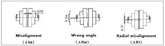
The centering should be carried out in two vertical planes perpendicular to each other. You can use the ruler (radial misalignment) and the feeler (angle of misalignment);
Unless otherwise specified, these parts may be preheated by induction heating, either by burner or by preheating in a heating furnace.
Installation of 1.3.2 hollow axle reducer (motor) with flat key
The solid shaft end of the working machine shall be fitted with the DIN6885 standard, the first part, A type flat keys, and shall have a central hole in its end face that conforms to the DIN standard, type 322 (DS);
Check whether the axle shaft and the working machine solid shaft have damage to the shaft seat and edge parts; if necessary, repair and clean with the appropriate tools;
The reducer is installed with nuts and screws, and the reaction force is provided by the hollow shaft of the reducer;
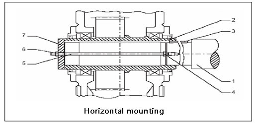
In addition to the nuts and screws shown in Figures 1 and 2, you can also use other types of devices, such as a hydraulic lifting device.
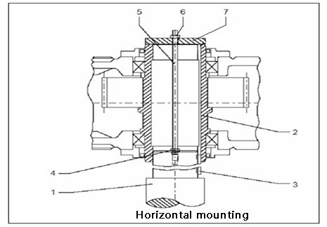
Installation of 1.3.3 expansion disc hollow shaft reducer
The solid shaft end face of the work machine shall be equipped with a central hole according to DIN standard 322 DS type;
Install with an integral bushing;
The reducer is installed with nuts and screws, and the reaction force is supplied by the hollow shaft of the reducer;
Install with loose bushings;
Push loose bushing onto the solid shaft of the work machine, secure it firmly with a positioning device, and then pull it along the shaft of the work machine into the hollow shaft of the reducer (refer to figures 1 and 2);
The outer surface of the hollow shaft of the reducer can be added with grease on the position of the shrink disk seat;
Tighten all fastening bolts one by one, and tighten all bolts after several cycles;
Tighten the fastening bolts until the front side of the inner ring and outer ring is aligned.